

『Inline Turbine Flow Meter: High-Speed Bladed Rotor Balancing Procedures for Low-Viscosity Fluids』Related information(v cone flow meter|rotary gas meter|gallon meter|gear meter|metal tube rotameter|glass tube rotameter|nutating disk meter|transit time ultrasonic flow meter|wedge flow meter|pd meters|hydraulic flow meter|ultrasonic water flow meter|water flow meter|air flow meter|magnetic water flow meter|oxygen flow meter|gas flow meter|argon flow meter|air velocity meter|gasoline flow meter|fuel flow meter|ultrasonic water meter|digital water meter|nitrogen flow meter|solid flow meter|Oxygen tank flow meter|digital water flow meter|diesel fuel flow meter|steam flow meter|02 flow meter|compressed air flow meter|oil flow meter|liquid flow meter)

Inline Turbine Flow Meter: High-Speed Bladed Rotor Balancing Procedures for Low-Viscosity Fluids
Quick Answer: Inline turbine flow meters with high-speed bladed rotors need static and dynamic balancing before calibration. Low viscosity fluids below 10 cP expose rotor unbalance quickly. Silver Instruments supplies balanced inline turbine meters from DN10 to DN300 with 4-20 mA HART output and 316L stainless steel rotors.
Why Rotor Balancing Matters in Low Viscosity Service
Low viscosity fluids such as naphtha, methanol, gasoline, diesel and solvents provide little hydrodynamic damping. A rotor with residual unbalance can vibrate at high speed. This vibration damages tungsten carbide bearings. It also produces uneven pulse signals from the magnetic pickup. In practice, an unbalanced rotor can reduce meter repeatability from ±0.1% to ±0.3% in the field.
We have seen this problem on a fuel blending skid in Vietnam. The meter was installed after a positive displacement pump. The rotor had a balance grade below ISO 21940 G2.5. The bearing failed after three months. The replacement meter from Silver Instruments had a balanced rotor assembly and the same installation worked for over two years.
What Changes in Low Viscosity Fluids
Low viscosity fluids, generally below 10 cP, allow rotors to spin at higher speeds for the same flow rate. A DN15 turbine meter can reach rotor speeds above 12000 rpm at 6 m/s. At that speed, a small mass error on one blade creates a large centrifugal force. This force is proportional to the square of the rotational speed. Many engineers skip this part because the rotor looks clean after machining. The real problem is not visible. It is the distribution of mass around the rotor axis.
Fluids with viscosity from 0.5 to 5 cP include light solvents, aviation fuel, kerosene and naphtha. Here is the thing. These fluids do not hide imbalance. They expose it.
High Speed Bladed Rotor Balancing Procedures
Silver Instruments balances each inline turbine rotor after machining and after assembly. The procedure follows four steps.
Step 1 is static balancing. The rotor is placed on a knife edge fixture. The operator adds or removes material at the hub. For DN15 to DN40 rotors, the static balancing tolerance is 0.05 g·mm per gram of rotor mass. Most machine shops skip this part because the rotor is small. We do not skip it.
Step 2 is dynamic balancing. The rotor assembly is mounted on a soft bearing balancing machine. The machine measures unbalance in two planes. The target balance grade is ISO 21940 G1.0 or better. For a rotor that weighs 0.15 kg and spins at 12000 rpm, the permitted specific unbalance is below 0.8 g·mm per kg. This is tighter than the standard G2.5 grade used for general rotating equipment.
Step 3 is final trim balancing. After the rotor is pressed onto the shaft and the bearings are fitted, the complete assembly goes back to the balancing machine. The trim pass corrects shaft runout, hub key effects and bearing preload. Final residual unbalance is verified at 3000 rpm because many turbine meters run at variable speed.
Step 4 is wet verification. The meter is tested with a low viscosity reference fluid. Water at 1 cP is not always enough. For solvent and fuel applications, we use a certified calibration fluid with viscosity of 1.5 cP at 20 °C.
_600x400.jpg)
Acceptance Limits and Tolerances
A balanced inline turbine flow meter should meet these typical limits. Accuracy is ±0.5% of reading for a 10:1 flow range. Repeatability is ±0.1% of reading. Linearity is ±0.25% for DN15 to DN50 meters. Pressure drop at maximum flow is below 0.3 bar for low viscosity fluids. The 4-20 mA HART output should show a stable signal with less than 0.05% full scale jitter.
For custody transfer or high accuracy batching, specify ISO 21940 G1.0 rotors. For standard process control, ISO 21940 G2.5 is acceptable. The cost difference is small compared to a failed bearing or an unplanned shutdown on a batch line.
Silver Instruments Inline Turbine Meter Models
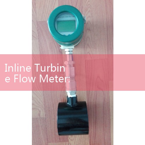
Silver Instruments supplies inline turbine flow meters with high-speed bladed rotors for low viscosity liquids. The SITB series covers DN4 to DN300. Wetted materials are 316L stainless steel rotor and 316 stainless steel body. Bearings are tungsten carbide with optional ceramic. Output is pulse, 4-20 mA HART or RS485 Modbus. Accuracy is ±0.5% of reading. Repeatability is ±0.1%. Temperature range is -20 °C to 120 °C. Pressure range is up to 10 MPa for DN4 to DN50.
For hazardous area service, Silver Instruments supplies ATEX Zone 1 and Zone 2 versions. A chemical distributor in the Middle East uses SITB-25 meters on methanol and acetone loading skids. A marine fuel supplier in Singapore uses SITB-50 meters for marine gas oil bunkering. Both applications involve viscosity below 3 cP at operating temperature.
Send us your fluid name, viscosity in cP, pipe size DN, flow range kg/h, pressure bar and temperature °C. Our engineers will propose a balanced inline turbine flow meter with the correct rotor and bearing combination. You can reach Silver Instruments by phone at +86-25-68650347, by Whatsapp at +86-25-52155837, or on WeChat at +86 15365082610. Please include your country and application in the first message.
FAQ: Inline Turbine Meter Rotor Balancing
What is the best balance grade for a low viscosity inline turbine flow meter? Use ISO 21940 G1.0 for DN15 and smaller high-speed rotors. For larger meters with lower rotor speeds, ISO 21940 G2.5 is acceptable.
Can a turbine meter handle viscosity below 1 cP? Yes. The rotor spins faster and the meter needs a tighter balance grade. Because low viscosity fluids provide poor lubrication, we specify tungsten carbide bearings and G1.0 balanced rotors for fluids such as liquefied gas or light naphtha.
How often should a high speed rotor be rebalanced? Rotors do not need rebalancing under normal operation. After a bearing replacement or if the meter output shows pulse jitter, send the rotor back for a trim balance inspection.
What bearing material is best for low viscosity fluids such as naphtha? Tungsten carbide bearings work well because low viscosity fluids provide poor lubrication. Ceramic bearings are an option for aggressive solvents or high purity applications.
What information do you need to quote an inline turbine meter for low viscosity service? Send fluid name, viscosity at operating temperature, pipe size DN, flow range kg/h or m3/h, pressure bar, temperature °C and the hazardous area zone if required.
 Hot Product
 Related AD