

『Flow Meter Upstream or Downstream of Control Valve Placement: Preventing Cavitation Errors』Related information(v cone flow meter|rotary gas meter|gallon meter|gear meter|metal tube rotameter|glass tube rotameter|nutating disk meter|transit time ultrasonic flow meter|wedge flow meter|pd meters|hydraulic flow meter|ultrasonic water flow meter|water flow meter|air flow meter|magnetic water flow meter|oxygen flow meter|gas flow meter|argon flow meter|air velocity meter|gasoline flow meter|fuel flow meter|ultrasonic water meter|digital water meter|nitrogen flow meter|solid flow meter|Oxygen tank flow meter|digital water flow meter|diesel fuel flow meter|steam flow meter|02 flow meter|compressed air flow meter|oil flow meter|liquid flow meter)
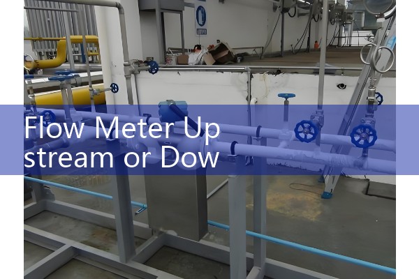
Flow Meter Upstream or Downstream of Control Valve Placement: Preventing Cavitation Errors
Quick Answer: Place the flow meter upstream of a control valve when you can provide 10 to 20 straight pipe diameters upstream and 5 diameters downstream. Mount the meter downstream only when back pressure stays above the liquid vapor pressure at all operating points. For steam and gas, upstream placement is the default. For hot water or chemicals near boiling point, downstream placement often causes cavitation errors unless you add a back pressure regulator.
We see this question on customer sites in Vietnam, Malaysia, Chile, and Saudi Arabia. The control valve is already installed. The flow meter arrives later. The plant engineer asks us if the meter can go downstream. The answer depends on the fluid, the valve type, the pipe layout, and the pressure drop.
Why Valve Position Changes Flow Meter Accuracy
A control valve creates turbulence. It also creates velocity profile distortion. Swirl and asymmetric flow produce measurement errors in vortex, electromagnetic, and turbine meters. Coriolis mass flow meters resist most profile distortion. But they still respond to two phase flow caused by cavitation or flashing.
When liquid passes through a valve, the local velocity rises at the vena contracta. Static pressure drops. If pressure falls below the liquid vapor pressure, vapor bubbles form. Downstream pressure recovery collapses these bubbles. The bubble collapse is cavitation. A flow meter placed downstream sees a mix of liquid and vapor bubbles. Most meters read this mixture incorrectly. A Coriolis meter may detect density change. An electromagnetic meter may read noisy flow. A vortex meter may count false shedding frequencies.
Upstream Installation: The Default Choice
Place the meter upstream of the control valve when possible. This keeps the meter in a single phase liquid or gas stream. The velocity profile is easier to correct with straight run. A typical recommendation is 10 straight pipe diameters upstream and 5 diameters downstream for an electromagnetic flow meter. For a vortex flow meter, use 15 to 20 diameters upstream and 5 diameters downstream.
In a gas line, upstream placement prevents pressure pulsation errors. A pressure reducing valve downstream of the meter can generate sonic flow at the valve throat. This noise travels upstream but the meter sees less disturbance than a downstream location.
Example from a sewage treatment plant in Indonesia: a DN200 electromagnetic flow meter was installed 12 pipe diameters upstream of a butterfly control valve. The meter accuracy stayed within 0.5 percent of rate from 20 m3/h to 400 m3/h. The same meter moved downstream of the valve gave scattered readings below 35 percent valve opening.
Downstream Installation: When It Can Work
Downstream mounting works only with enough straight pipe after the valve and enough back pressure. You need 10 to 15 pipe diameters of straight run downstream of the control valve before the meter. The straight run lets the flow reattach and the velocity profile recover.
For liquids, calculate the pressure at the meter inlet. It must stay at least 1 bar above vapor pressure, or 0.3 bar minimum for cold water. For hot water above 90 °C, use more margin. A back pressure control valve or a restriction orifice downstream of the flow meter can raise static pressure.
A palm oil plant in Sabah, Malaysia ran a DN40 Coriolis mass flow meter downstream of a globe valve. The line pressure was 4 bar. The oil vapor pressure was low. The meter worked because the liquid stayed in single phase. The same setup failed on a hot condensate line at 140 °C because the downstream pressure dropped below vapor pressure at high valve lift.
Preventing Cavitation Errors
Cavitation starts when local pressure falls below vapor pressure. You prevent it by maintaining back pressure, reducing valve pressure drop, or moving the meter upstream. A flow meter cannot fix cavitation. It only reports the error.
For steam and gas, the error shows as density change and volume flow error. A mass flow meter with pressure and temperature compensation helps, but the best fix remains layout. Use a straight run spool piece if you have no room. Install a flow conditioner upstream of the meter only if the manufacturer allows it.<
For a chemical plant in the Philippines, we supplied a DN80 vortex flow meter with integrated PT100 temperature sensor and 4-20 mA HART output. The meter was placed 15 diameters upstream of a pressure control valve. The liquid was xylene at 40 °C. Cavitation errors disappeared after the plant moved the meter from downstream to upstream.
Selecting the Right Flow Meter by Valve Position
Electromagnetic flow meters work well upstream on conductive liquids. Choose DN15 to DN300 sizes with PTFE liner and 316L electrodes for clean water, wastewater, and chemicals. They need full pipe and straight run.
Vortex flow meters work on steam, compressed air, and clean liquids. Use them upstream of control valves where possible. A vortex meter downstream of a valve needs a long straight run and should not be used if cavitation or flashing is likely.
Coriolis mass flow meters handle short straight runs and can measure mass flow, density, and temperature. They cost more but they tolerate disturbed profiles better than volumetric meters. Place them upstream or downstream as long as the fluid stays in single phase. On flashing services, use upstream installation.
Oval gear flow meters are positive displacement and work well on diesel, fuel oil, and lubricants. Install them upstream of a control valve with a filter to keep solids out. For high viscosity fluids above 100 cP, positive displacement meters provide better repeatability than turbine meters.
Thermal mass flow meters work on gas lines. A thermal mass flow meter should be placed upstream of a pressure control valve to avoid temperature and pressure swings at the sensor.
Industry Notes
Water and wastewater plants in Australia and New Zealand usually install electromagnetic flow meters upstream of control valves. This matches local water authority standards that require 10 diameters upstream and 5 diameters downstream.
Oil and gas terminals in the Middle East often use Coriolis mass flow meters on LPG and fuel oil. The meters sit upstream of pressure reducing valves. This prevents two phase LPG from reaching the meter.
Food and beverage plants in Latin America use sanitary electromagnetic flow meters. Place these upstream of the divert valve to keep the meter full during product changeover.
Chemical plants often handle hot liquids near boiling point. For these lines, do not mount the flow meter downstream of a control valve unless you add a back pressure device and verify the minimum pressure at the meter inlet.
FAQ on Flow Meter and Control Valve Placement
Can I install a flow meter downstream of a control valve? Yes, if the fluid stays in single phase and you provide 10 to 15 straight pipe diameters between the valve and the meter. Add a back pressure regulator if needed.
Which flow meter works best upstream of a control valve? Electromagnetic, vortex, Coriolis, and thermal mass meters all work well upstream. The choice depends on fluid conductivity, temperature, pressure, and pipe size.
What causes cavitation errors in a flow meter? A control valve drops pressure below vapor pressure. Vapor bubbles form and collapse. The meter sees two phase flow and reports high or unstable readings.
How much straight run do I need upstream of a control valve for an electromagnetic flow meter? A typical figure is 10 pipe diameters upstream and 5 diameters downstream. Some plants use more for high turbulence or disturbed profiles.
Does a Coriolis mass flow meter need straight run upstream of a control valve? No, it tolerates short straight runs. But it still needs single phase flow. Avoid mounting it downstream of a valve that causes flashing or cavitation.
Get a Flow Meter Quote from Silver Automation Instruments
Send us your fluid type, pipe size, pressure, temperature, and flow range. We will recommend a meter and the correct installation position relative to your control valve. We ship to Southeast Asia, Oceania, Latin America, Africa, and the Middle East.
Tel: +86-25-68650347
Whatsapp: +86-25-52155837
WeChat: +86 15365082610
Silver Automation Instruments. Industrial flow meters and process instruments for control valve upstream and downstream applications.
 Hot Blog
 Related AD